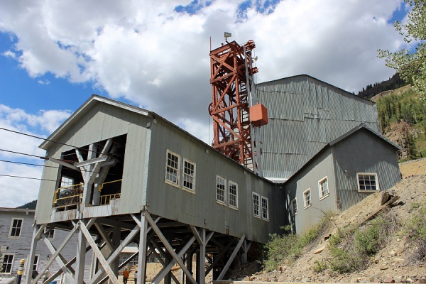
The Mayflower Mill is a must see to learn about the metal processing and mining within the San Juan Mountains of southwestern Colorado. The mill is located off of CR 2 (aka Alpine Loop Scenic Byway) approximately 2.5 miles from downtown Silverton.
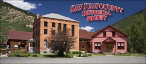
San Juan County Historical Society PO Box 54
Silverton, CO 81433
970-387-0294 (Mill Phone)
970-387-5838 (Society Phone)
www.sanjuancountyhistoricalsociety.org
The following information is brought to you by the San Juan County Historical Society.
Most ore coming from mines have a high percentage of waste rock mixed with the metals. The purpose of the mill is to eliminate as much of this waste from the ore as possible before sending the mineral concentrates to a smelter for final purification.
The Mayflower Mill is a Selective Flotation Mill, meaning that it was designed to recover the minerals by floating them to the surface of water in cells with reagents, and separating the respective metals from others into their own concentrate.
The ores of the San Juan Mountains are classified Complex-Sulfide Ores (mixed metal containing Sulfur). The 5 major metals mined and milled commercially are Gold, Silver (Precious Metals), Copper, Lead and Zinc (Base Metals). Some minor metals have been Tungsten, Nickel, Manganese, Cadmium and Cobalt. Iron Pyrite ("Fool's Gold") is the most common metal found and runs with the other ores, but is not mined commercially.
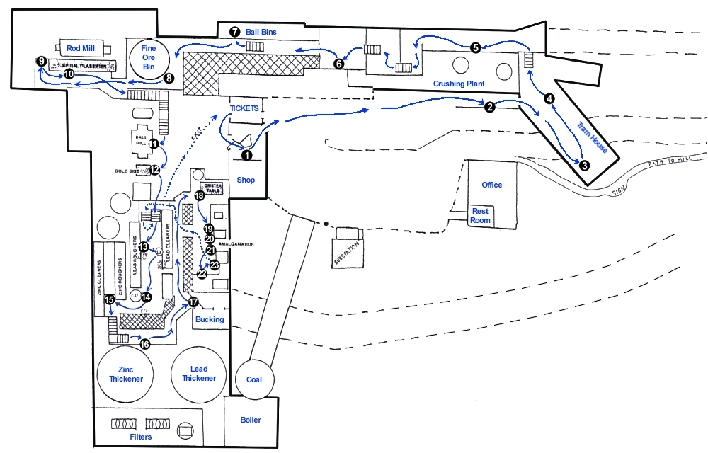
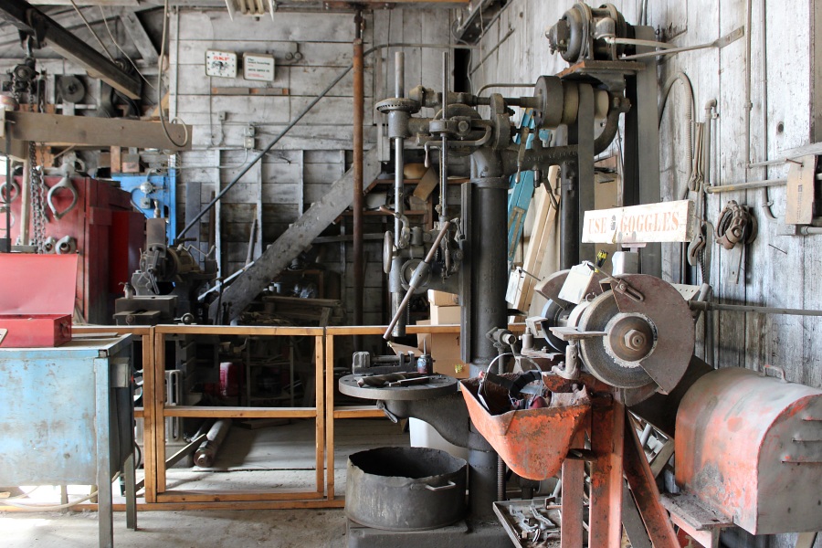
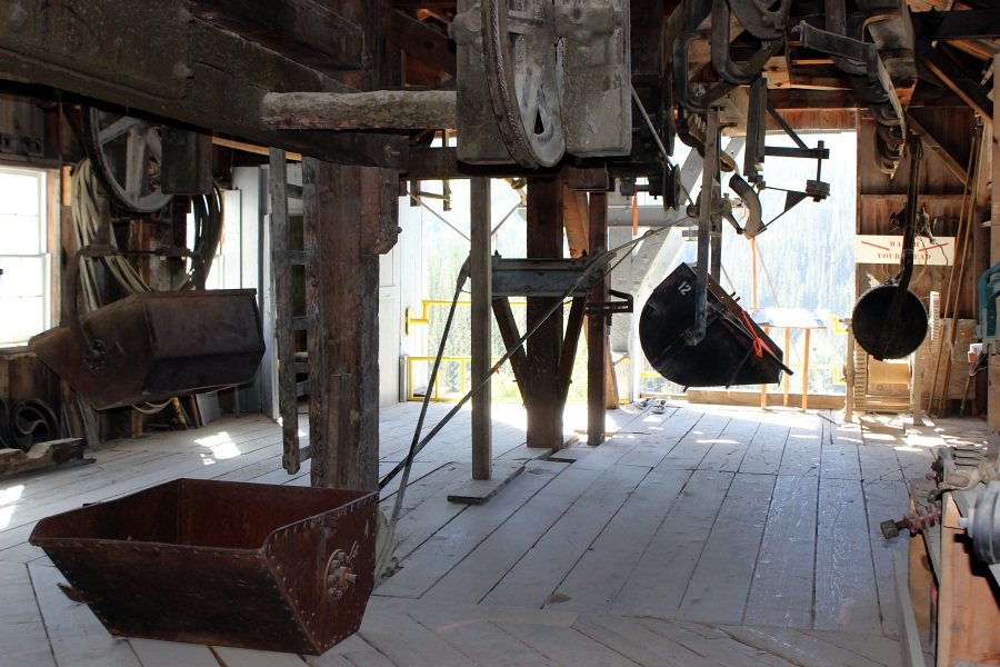
Station 1. Machine Shop
Centrally located, this was the area where the shift changes took place and the strategy for the day laid out. This was also the home of the Maintenance Crew of 6 to 8 men whose sole responsibility was to keep the mill running and in good repair.
The major pieces of machinery of the shop are the metal lathe, the shaper, the drill press and the electric arc welder. They were new when installed in 1929 after the construction of the mill. Although over 60 years old, they were still being used daily when the mill was closed in 1991. Even today they are used on occasion.
The shop could make almost anything needed to keep the mill running. Beside the mill maintenance, the crew built and repaired equipment for the mine as well. Like other small communities, the shop was used on many occasions to keep projects going in town as well, and with the blessings of the Company.
Station 2. Sighting Pipe
The sighting pipe provides a view of the tram way.
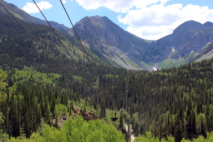
Station 3. Mayflower Aerial Tram
Designed by Stearn-Rogers Co. of Denver and built by Fred C. Carstarphen in 1929, the tram's purpose was to transport ore from the mine to the mill and carry supplies back up.
Employees rode (two per bucket) by placing a small board across the inside of the bucket for a seat and covered themselves during the winter months with a heavy blanket that was provided by the company.
The principle of the tram system is relatively simple. The bucket was designed with Double Trucks (4-wheels) which rode over a large steel cable called the Stationary Cable. Each bucket was pulled along by another cable called the Traction Rope. The bucket was attached to the traction rope with a gripper, which automatically "gripped" and self-gripped itself as it entered or left the Tramhouse.
The tram was run and controlled on the mine end. The drive machinery consisted of two 50 HP electric motors - one Synchronous motor with a speed controller and one Induction motor with no controller. To start the tram in motion the Synchronous motor was brought slowly up to 3/4 speed with the controller. At that point the Induction motor was started and the two motors took the tram up to full speed, a little over five miles per hour. These motors put the Traction Rope into motion, which pulled the buckets along the top cable.
As the buckets were loaded with ore and put on the line for their trip down to the mill, the weight of the descending buckets wanted to move the tram at a higher rate of speed due to the pull of gravity. From that point on the two drive motors would come into use as a breaking system to keep the tram at constant speed. There were also two electric brakes on the systems which were used in case of an emergency or to hold the tram stationary if shut down. At full speed the tram made a complete circle (mill to mill) in 45 minutes.
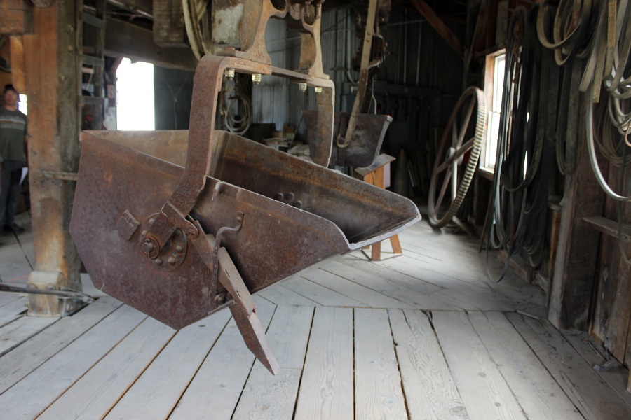
Station 4. Old Tram Bucket Display
The small bucket is a Huson Bucket by the Hallidie Co. This was the first aerial tram system used in the Silverton area. They had a capacity of around 150 lbs. of ore and were used extensively from the 1870's into the 1890's. This was a one-cable system. Notice that they had no trucks (wheels) to run over the cable as the other buckets. The bucket was attached directly to the traction rope (drive cable) as can be seen in the example of the gripper bolted to the cable lying over the bucket. This is similar to the systems used for chair lifts at our "modern" ski resorts today.
The larger bucket is a Bleichert Bucket by the Trenton Iron Works in New Jersey. This system started coming into use in the 1890's and was widespread and very popular. The capacity of the bucket was approx. 350-400 lbs. of ore. Notice that it was designed with one set of trucks (wheels) to run over a stationary cable and pulled along by a traction rope, as were the much larger Mayflower buckets. These buckets were also used to carry men and two men to a bucket were not uncommon. When carrying two riders, one or both would either sit on the edge or stand up hanging onto the bail. This system lasted well into the 20th Century and was never really replaced until the Mayflower Tram was built.
Station 5. Crushing Plant
In 1959 Standard Metal Corp. purchased both the Mayflower Mine property and the Sunnyside Mine. While the "new" Sunnyside was being developed for production, limited ore was coming down over the tram from the Mayflower Mine. Since this ore was already crushed to a gravel size material at the Mayflower Mine, it went directly into the mill for processing.
In 1963, with the Sunnyside coming into production and no crushing facilities at the mine, this crushing plant was built for that purpose. The ore was shipped down from the mine in trucks.
The trucks dumped their ore in a chute behind this building, a conveyer belt carried the ore into the plant and dropped it into the Primary Crusher which was a Telsmith 25" X 36" Jaw Crusher (No. 2). Rock leaving this crusher was broken down to baseball size material or smaller.
Leaving the Jaw Crusher, the broken rock was carried up to a screening process for sizing. If it was small enough to pass through the vibrating screen (approx. 1-1/4" or smaller), it was conveyed directly into the mill. If the rock rode over the screen it was carried by conveyer belt to the two Secondary Crushers for more crushing.
The two Nordberg Symons Cone Crushers were called Bell Crushers because of the shape of their interior jaws. With the ore riding over the top conveyer, the rock dropped down the funnel into the top of the crusher. There it passed between the two interior jaws set to break the rock down to the required size. Passing on through, the material fell down onto the conveyor belt (No. 4) and was carried up to the top of the mill and deposited in the Fine Ore Bin, a holding facility. The Crushing Plant could break enough rock (1,200 tons) in two 8-hour shifts to keep the mill running for 24 hours.
Needless to say it was dusty and quite loud when the plant was in operation. Even though there was a vacuum system to help eliminate dust, the three required operators wore both ear and respiratory protection. The plant is equipped with two 5-ton moving overhead hoists that were used to repair and/or replace machinery when necessary.
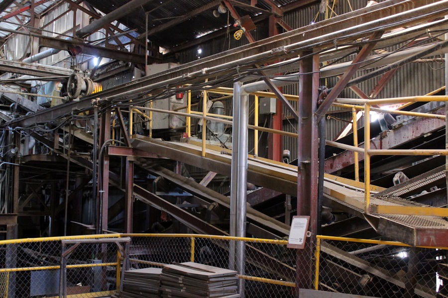
Station 6. Conveyer Belt System
With conveyer belts running in every conceivable direction, it can seem confusing for anyone not familiar with the system. In short a series of belts carried rock from one location to another, either screening or crushing it until it was small enough to enter the mill.
The last belt that carried the final product to the top of the mill is the far one against the wall. Passing up and through the belt ramp the crushed ore was dropped into the top of the Fine Ore Bin, which was used as a temporary holding facility before the processing began.
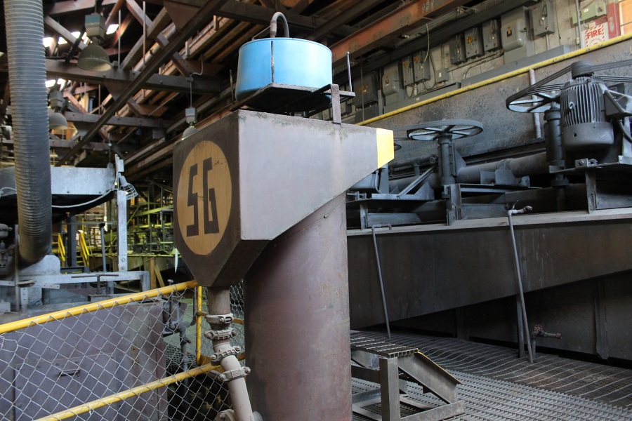
Station 7. Steel Ball Bins
The steel balls seen here were used in the Ball Mill grinding process of the ore. This was the storage location for the two different sizes used, that were 2" and 3" in diameter.
As the balls were needed on a daily basis, they would be dropped into the pipe where they would roll down by gravity and automatically deposit themselves in the Ball Mill.
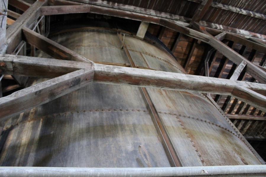
Station 8. Fine Ore Bin
This was the holding facility for all of the crushed ore coming from the Crushing Plant. As the gravel size material was deposited in the top of the tank from the conveyer belt, three steel chutes in the bottom of the tank metered the ore onto another belt to carry it into the Rod Mill to begin processing.
The bin has the holding capacity of 1,200 tons, enough to run the mill for one 24-hour period. Note: The Bin still holds approx. 800 tons of crushed ore to this day.
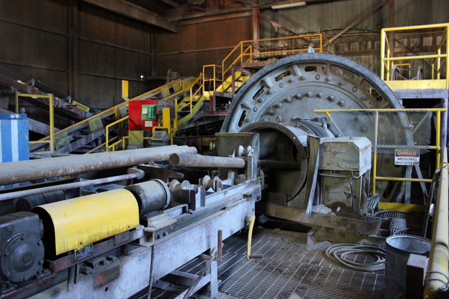
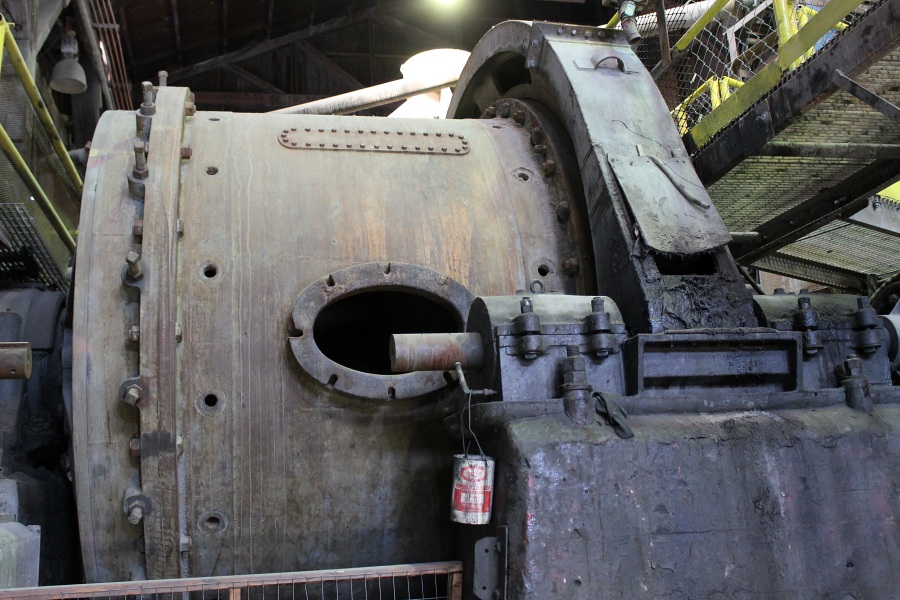
Station 9. Rod Mill
Called a Rod Mill because it is charged (loaded) with approximately 192 solid steel rods weighing 48 tons. Each steel rod is 11'8" long x 3" in diameter and weighed 500 lbs. With the rods loose and the mill rotating clockwise, it acted like a giant tumbler grinding the gravel down to a sand-like consistency. Like all moving parts in a piece of machinery, the rods would wear down to small irregular pieces and discharge out the front of the mill to be discarded. In order to maintain the initial 48 tons of weight, 2 to 3 rods were charged into the mill daily.
With the Rod Mill running, the ore was continuously fed into the back from a conveyer belt. It was here that water was first introduced to the dry ore entering the mill. With the rods falling upon one another, the ore was ground down and forced to the front of the mill and discharged through a Launder into the Spiral Classifier (Station 10).
Note: From this location and through the entire mill, all of the ground ore was mixed with large amounts of water that gave it the look of a dark gray dirty liquid. This color was due to the pulverized metals. Through its entire process of mineral separation the mill used around 1,400 gallons of water per minute. The water for the mill came from Arrastra Gulch, the same gulch that the Mayflower Mine is situated in.
A 400 H.P. Falk motor & Gearbox powered the Rod Mill.
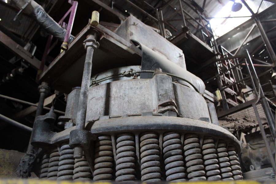
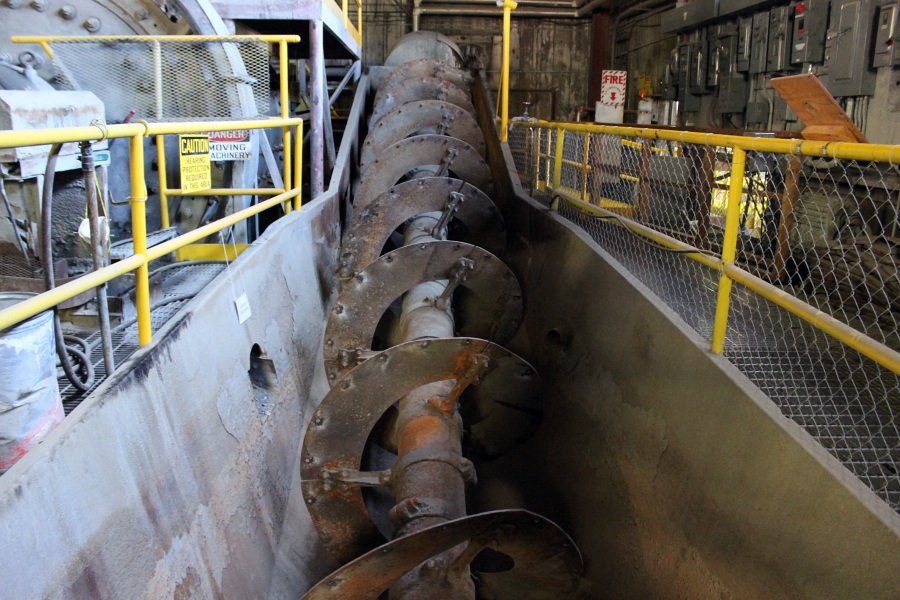
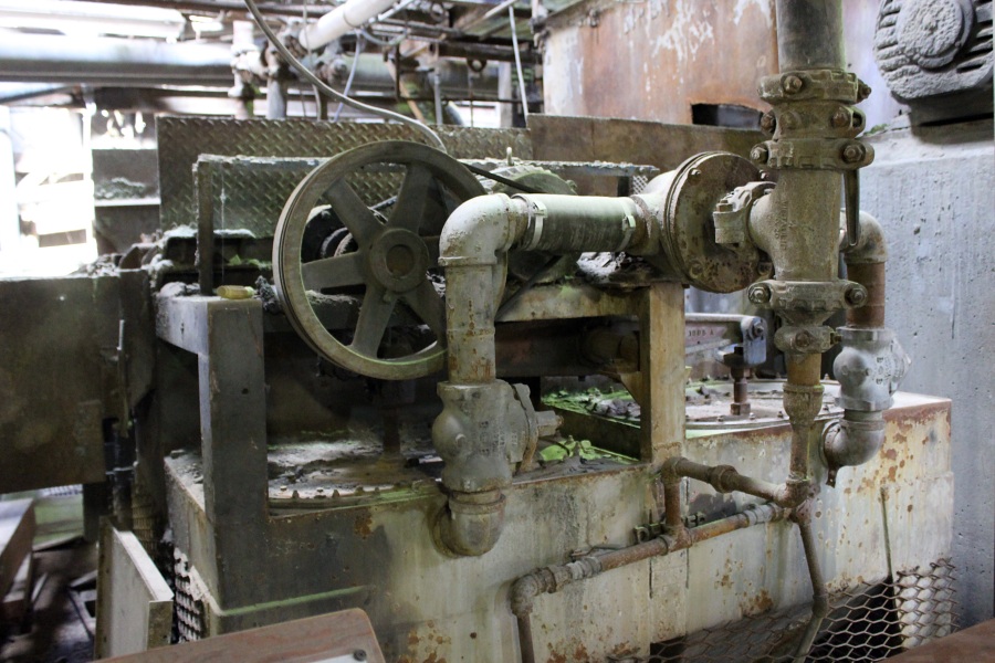
Station 10. Spiral Classifier
All of the sand/water solution entering the Classifier was immediately graded by weight. If the sand was fine enough it would flow with the water up and over the bulkhead (lower end) and would immediately descend through a pipe to the Gold Jigs below to start the mineral separation. The coarser sand that was too heavy to flow with the water would drop to the bottom of the liquid and be spiraled up to the top of the Classifier where it was piped down to the Ball Mill for further grinding.
Station 11. Ball Mill
This was the final step of the grinding circuit. This mill, while rotating would re-grind the coarser material coming down from the classifier to the required fine sand needed to liberate the remaining metal sulfides.
The mill was charged (loaded) with 25 tons of steel balls (2" and 3" in diameter). These balls would wear down and in order to maintain the initial weight, 50 new balls were charged into the mill daily, rolling down through a pipe from the Ball Bins above.
All of the material (Pulp) discharging from the mill would immediately enter the Gold Jigs (Station 12).
Station 12. Gold Jigs
The first of the five metals to be separated and saved, as Gold was the heaviest. All material leaving the Ball Mill as well as that coming directly down from the spiral classifier flowed through the Jigs. Approx. 70% of the Gold along with portions of other metals (mostly Iron) were picked up here and pumped over to the jigs holding tank.
The jigs were strictly mechanical. The heavy gold would drop through a screen enhanced by vibration and suction created by the diaphragms attached to the rocker arms.
Gold Jigs Tank directly was the holding facility for the Gold Jigs. From this tank the jigs dropped down to the Amalgamation Department to start the purification process of the Gold. This will be seen further into the tour.
Lead Conditioning Tank: (not visible from this location) All the solution passing through the Jigs were dropped down to this tank. As the material was being agitated, Reagents were added, preparing the metal sulfides for their first separation in the flotation process. From here the solution was pumped up to the Lead Rougher Flotation Cells (Station13).
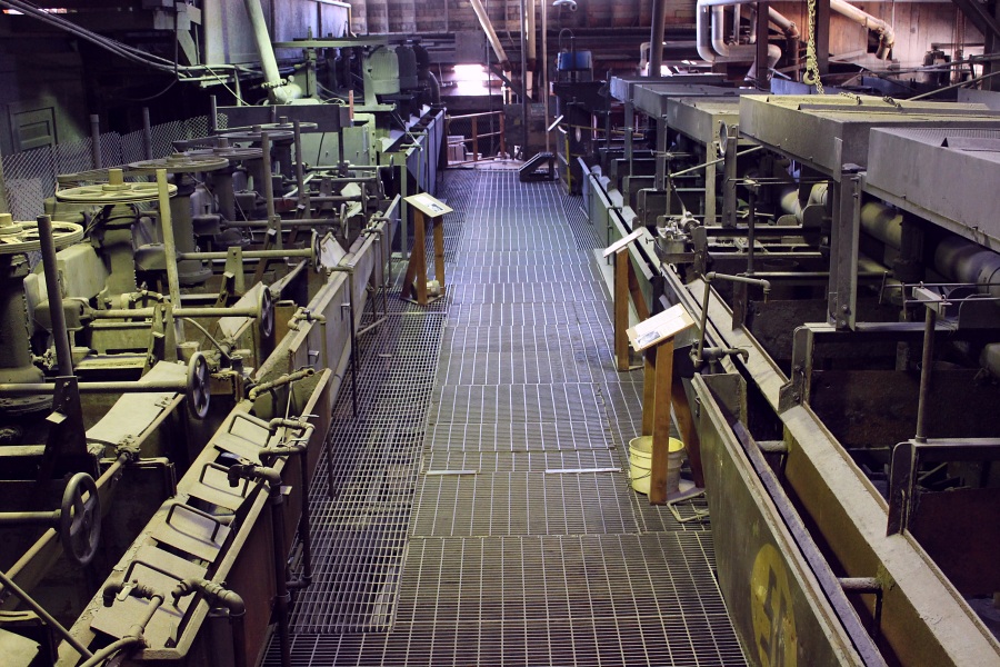
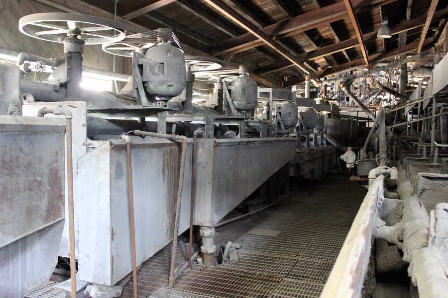
Station 13. Lead Flotation Cells
The bulk of the Lead, Silver, Copper and most of the Gold that escaped the Jigs was floated in these cells. The Zinc, along with the Iron and other waste material was depressed and pumped over into the Zinc Conditioning Tank.
The floated material coming off these Roughers came to the surface of the liquid rapidly and in large bubbles. Here it flowed over into the front launder (trough) and was pumped to the Lead Cleaner Cells.
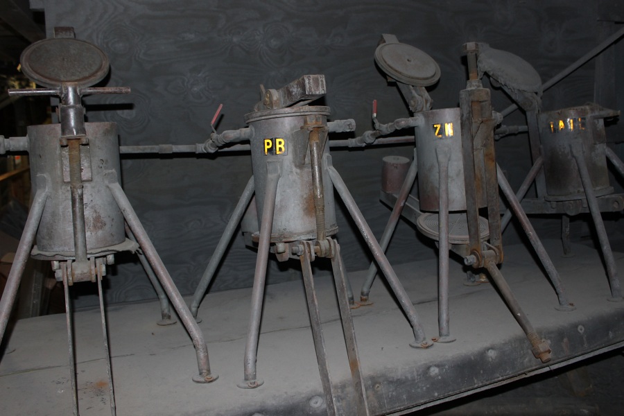
Selective Flotation
The process of whereby pulverized Sulfide Ores (metal mixed with Sulfur) are separated from other metals and waste material by making them come to the surface of the water with the use of Reagents called Collectors. Different reagents were used for different metals. The floated mineral is skimmed from the surface of the liquid into its own concentrate. The remaining metal(s), which are kept to the bottom of the cell with reagents called Depressors, moved on to other cells for their own separation.
The reagents used in the mill are broken down into three classes:
Collector: A reagent that has an affinity for a particular metal(s), which attaches itself to an air bubble that, carries the metal to the surface of the water to be skimmed off.
Depressant: A reagent that coats a metal(s) and keeps it submerged in the bottom of a float cell.
Frother: A reagent to help form air bubbles and make them more susceptible to the collectors.
All waste material leaving the Lead Cleaners was pumped to this, the last of the Lead Cells. Scavengers were used to recover any Lead, Silver, or Copper that may have escaped the Cleaners. Any metal picked up here was pumped back to the Lead Conditioning tank to be re-circulated, while the Zinc and waste material remained depressed and was pumped to the Zinc Conditioning Tank.
Station 14. Copper Flotation Cell
The copper was separated here from the Lead concentrate. With the Copper being a small percentage of the two metals, only one cell was required for separation. This is a vertical type cell extending down three levels, as compared to the Lead and Zinc cells, which are horizontal. The principal was basically the same as the other cells, applying reagents to depress the Lead and air to allow the copper mineral to rise to the surface in the form of froth. Now separated, the copper mineral flowed up over the top of the pipe into the catch box. This concentrate was piped down to the Copper Filters for final treatment, while the Lead Mineral concentrate went to the Lead Thickener Tank to start the de-watering process.
Zinc Conditioning Tank (Not visible from this location)
All of the material (Pulp) that had been depressed in the Lead Cells was then dropped down to another conditioning tank below this floor to prepare the Zinc Mineral (the only metal left to be saved) for flotation. Having been depressed in the Lead Cells, the chemistry was changed so the Zinc could now be floated to the surface with a different Collector Reagent. This material was then pumped up to the Zinc Rougher Cells.
Station 15. Zinc Flotation Cells
Zinc was the only commercial material metal left to recover from the pulp, and was floated here along with any remaining Gold. The froth was pumped over to the Zinc Cleaners. All of the remaining material was sent over to the Scavenger Cells for a final cleanup of any remaining minerals.
Zinc Cleaner Cells
Here the Zinc was concentrated by eliminating any waste material that may have escaped the Rougher Cells. The concentrated Zinc Mineral was dropped down to the Zinc Thickener Tank to start the watering process. All other material was sent to the Scavenger Cells.
Zinc Scavenger Cells
Any remaining metal was picked up here and pumped back to the Zinc Conditioning Tank to be re-circulated. All of the insolubles (waster rock) and the vast majority of Iron (considered a waste product) were dropped down to a retaining tank where it was picked up and pumped out to the Tailing Pond for disposal.
This was the last of the Flotation Process. When running well, the mill had a recovery rate of 90 to 91%, considered excellent for the industry.
Station 16. Thickener Tanks
Directly below is the Zinc Thickener Tank. In the shadow on the same level, is the Lead Thickener. Now empty, the two tanks when being used would have been full or water. The purpose of the tanks was to eliminate water from the Mineral Concentrates flowing into them from the Flotation Cells.
The principle of the Thickener for de-watering was simple. With the tank already full of water and as more concentrates in solution were deposited into the tank, the heavy mineral would immediately drop to the bottom. With no place for the water to go, it overflowed the edge of the tank into the Launder which surrounds the perimeter. This water solution was discarded as a waste and pumped out to the Tailings Pond for disposal. About 90% of the water was eliminated in this manner.
With the rakes slowly rotating to keep the concentrate from caking to the bottom of the tank, the thickened mineral solution was forced to the center of the tank by the rake. Here it dropped through the funnel-shaped outlet in the bottom to be pumped down with a limited amount of water to the filters below for final separation of mineral and water.
Each mineral concentrate piped down to its own filter bank on the next level; here the remaining water was eliminated.
With the filter wheels in constant rotation on an axle, they would pass through the thick mineral solution. With a vacuum drawing the solution onto the canvas filter, the water passed on through the canvas to be discarded. The mineral unable to penetrate the filter was scrapped off before entering the solution again on another revolution. This semi-dry concentrate dropped down to a holding bin directly below.
This was the last step of the milling process. The mill could remove most waste from the metal except sulfur. This required large amounts of heat and could only be done at a smelter. For many years the concentrates were shipped to the smelters by rail but in later years everything was trucked.
Station 17. Sample Bucking
Although not directly related to the milling process, this was an important department for the mining company. It was the location where the entire daily mill and mine samples were prepared for assaying (the process of determining the kind and amount of metal in a given sample).
All samples going to the Assay Lab had to be dry. With most of the mill samples wet or in solution form, the first step of eliminating water was putting them in the presses. With most of the water now pressed out but still damp, the samples were spread out in trays and completely dried in the ovens in the adjacent room. There they would be split and put in envelopes, half going to the Lab for assaying, the remainder kept as a backup.
The mine samples were dried if necessary and then pulverized into powder with half also sent to the lab.
Within one to two days the results from the Assay Lab would be obtained. It was the results of these assays that gave the Company the information needed to determine the grade of ore coming from the mine and daily milling results.
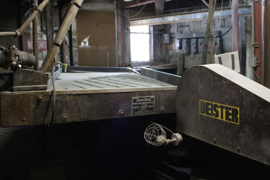
Station 18. Deister Table
As previously mentioned, the material from the Jigs was deposited in the Holding Tank sitting above this room. The funnel-shaped container in the cutout on the far wall is the bottom of that tank.
As the material dropped from the funnel it was mixed with water and piped to the Deister Table. With the table shaking and a film of fresh water washing down over the table, the Jig material immediately started spreading out over the surface. As the material began working its way over the riffles and towards the right hand end, the water washed the lighter particles over the bottom edge to be shipped back into the milling process.
The Gold and Lead stayed high on the table and separated themselves into two distinct bands of concentrate. Most of the Lead was also saved with the Gold since the two metals are very close to the same weight and become mixed as they came together. These two metals would fall off of the end of the table into a trough to be deposited into the steel Jig Con Boxes you see here on the floor. With the contents assayed (a process to determine the amount of Gold) and then weighed (usually about 1-ton) a box was picked up with the Chain Hoist you see here and transported over the monorail into the next room to start the Amalgamation process.
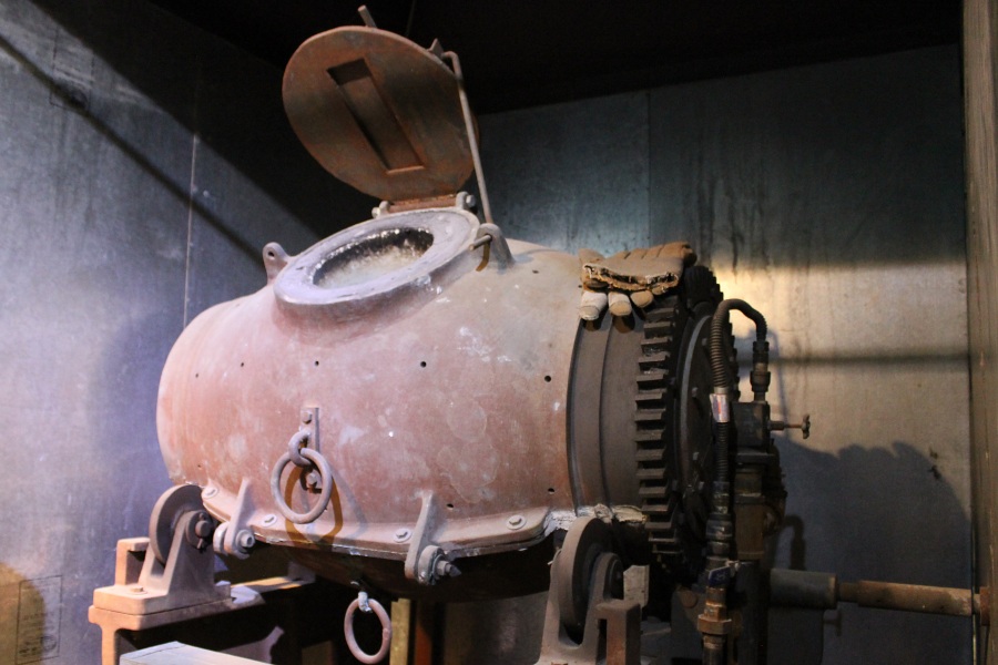
Station 19. Amalgamation
With a Jig Con Box placed onto the framework above the Amalgamation Barrel, all the material was washed into the barrel with a water hose. The barrel already contained 1,250 lbs. of steel balls, 90 lbs. of various powdered cleaning agents were added. This process was called "Charging". The barrel was then filled with water, the door closed, and rotated for 3 hours on high speed. At the end of this period, approx. 80 lbs. of Mercury was added, the amount determined by the ounces of Gold involved. This final mixture was again rotated for 3 hours but on a lower speed.
During the amalgamation process the contents were ground to a fine consistency. The Gold particles were cleaned, and the Mercury absorbed all of the Gold and any Silver in the Barrel. Since the Mercury would not pick up any other metal or waste, this material was eventually recycled back into the mill.
Station 20. Alutriation
At the end of the seven-hour rotation period the barrel was stopped. The liquid (Mercury and water) was slowly emptied through a small porthole in the barrel into a piece of machinery on the floor below called an Alutriator. This was a simple process similar to a Cream Separator in the sense that all of the liquid swirled around the inside throwing the water and any light material to the side, allowing heavy Mercury saturated with Gold to drop straight through into a bucket at the bottom.
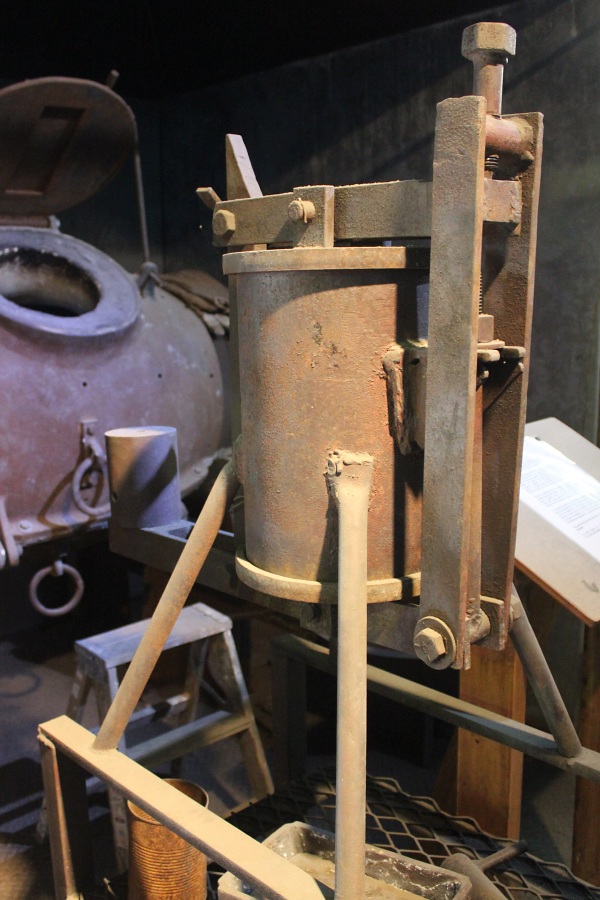
Station 21. Amalgam Press
With a fitter placed on the perforated bottom door and closed, the thick Mercury-Gold mixture from the Alutriator was poured into the top of the press With the top door closed, compressed air was supplied to the press, which forced the excess Mercury to pass through the filter and drop into a bucket of water. This procedure was called "Pressing Cakes", and took from 20 to 30 minutes. At this point the air was turned off and bled and the press opened up.
The product was a semi-hard cake the circumference of the press and several inches thick depending on how much gold was present. The color was pewter gray since the gold particles were still covered with a thin film of mercury. This substance was called Amalgam. The word actually means, "Mercury mixed with metal". You can also make a Silver Amalgam or Copper Amalgam since Mercury will pick up these metals as well.
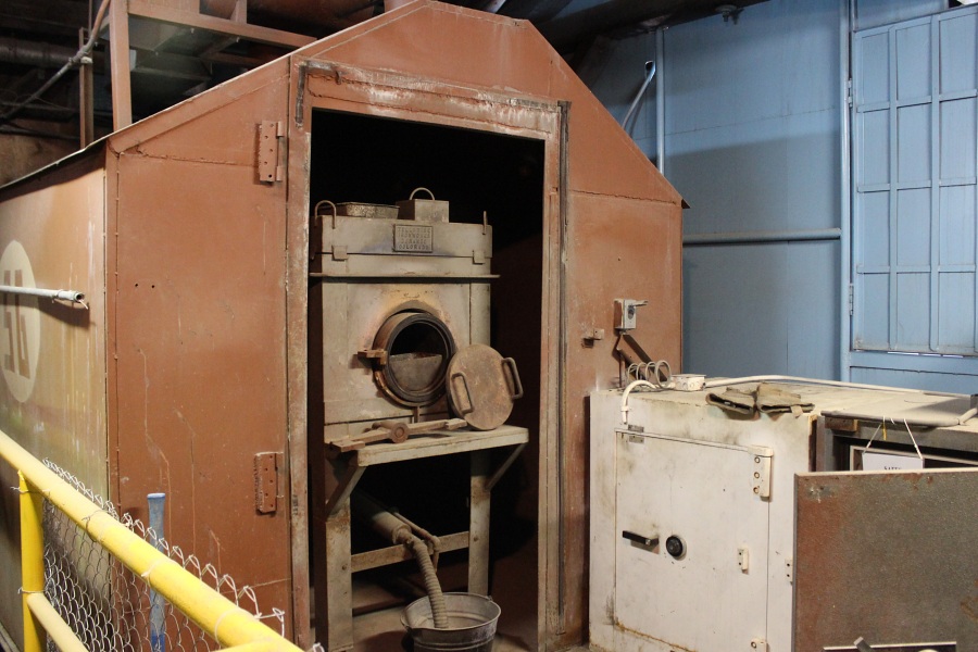
Station 22. Retort
The retorting of the Gold was the last of the 5-steps in refining the metal here in the Mayflower Mill.
The Amalgam Cakes were taken from the press to the table and broken down into small pieces. These pieces were placed in the steel half moon shaped vessels called Boats. The Boats were 3/4 full when they were placed in the Retort Oven. With the door closed and sealed with a Fire Clay compound (to make it airtight) the heat was turned on.
The principle of the oven was to evaporate the Mercury from the Gold, called "Cooking" or "driving off Mercury". As the temperature rose the Mercury would start changing into a vapor form. This vapor (extremely poisonous) would go through a water cooling system that condensed the vapor back into a liquid that would drop into a bucket of water at the bottom of the retort oven. After approx. 12 hours with the temperature held at 1,200 degrees Fahrenheit, the Mercury would be completely driven off. The Retort would then be turned off and allowed to cool, requiring another 12 hours.
With the oven opened the Boats would be taken back over the table and with a sharp blow from a hammer the Gold bar would fall out. This chunk of metal was called a Sponge since it was only 70% to 90% Gold with the remainder mostly Silver and some Copper. This was as far as the Company processed their Gold. The Sponge was then sent to a foundry where it was refined into Bullion that was 99.9% pure. An interesting comparison: Jewelry Gold is measured in Carats. Twenty-four (24) carats is pure gold. The average piece of jewelry is 14 carats, approx. 58% gold.
On the table with the Boats is a replica Gold Sponge as it would look coming from the retort. The average size would weigh 221bs. If containing 80% Gold and sold at $300 per Troy oz., the sponge would be worth $63,200. Four to five sponges were produced a week.
Photos by EMKotyk
Station 23. Bullion Furnace
This Propane fired furnace was installed the last year the mill operated (1991). The purpose was to eliminate the Amalgamation Process, which used Mercury to pick up the Gold.
This furnace was designed to take the concentrated Gold Jigs direct from the Deister Room. The principle was to melt down all of the metals including any waste in the furnace. As the contents became molten, they would separate themselves into different layers according to weight The Gold being the heaviest would go to the bottom. At a given temperature the door would be opened and the furnace rotated on the axle while pouring the layered molten material.
The first out would be the slag (waste rock) poured in the large cone shaped metal vessel where it would eventually be discarded. Next were the lighter metals. Last would be the Gold almost in a bullion state (99% pure) poured in the cast iron bullion bar containers marked with Oz amounts as seen on the floor.
The process would have been the safest method of making Gold bars since it eliminated the Mercury. Unfortunately, this process did not come into regular use before the mill shut down. The Echo Bay Mining Company, the last operators of the mill, ceased mining in the San Juan Mountains due to the drop in base metal prices and environmental requirements which became so expensive.